Specifications
|
DJI, the sponsoring team, has requested deliverables for the project:
|
Concept Generation
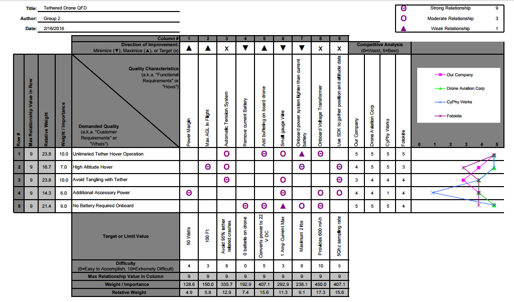
Based upon the QFD chart shown beow, we determined that our top priorities are unlimited tether hover operation, avoiding tether entanglement, and no battery on board. After determining the main metrics for this project, we decided to look at existing solutions. Many drone companies have already implemented a power tether. However, we can improve upon it by increasing the amount of power transmitted to well above the maximum required power of the drone. Many of these tethers do not allow for 100 feet hover,
something we look forward to achieving.
something we look forward to achieving.
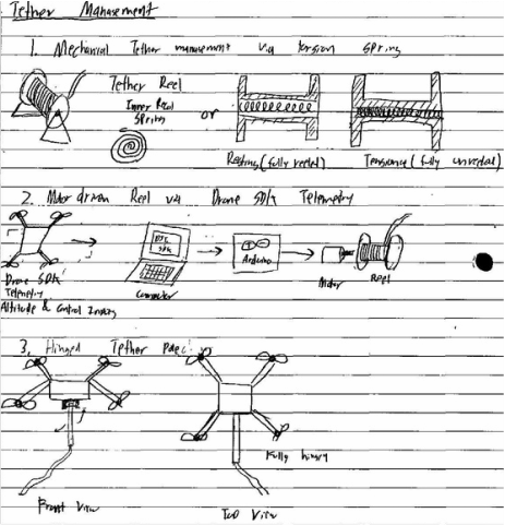
Some example concepts we came up with included a reeling mechanism with thin wire that uses constant tension to minimize slack on the cable without pulling on the drone and affecting its flight characteristics. A similar idea used the DJI SDK to control the reeling mechanism based on GPS and controller data. All of our concepts can be seen in the drawings below
|
|
Concept Selection
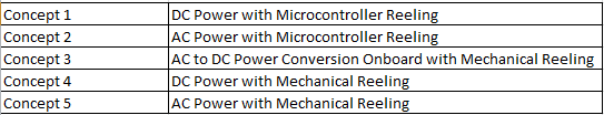
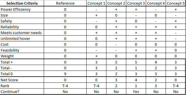
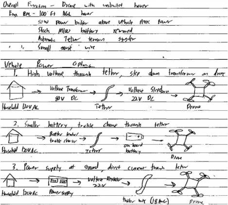
Based on our customer needs from DJI we came up with five preliminary concepts. The major decisions that we had to make were whether to use AC or DC power through the tether and how the reeling mechanism will work. If we were to use DC power, we would not need to convert the power onboard, a system that would add weight to the drone. However, sending 500+ Watts of DC power would require a
heavy gauge wire and would be unsafe if the wire was disconnected. Thus, we decided to send high voltage AC power through the tether cable and then convert it onboard to DC.
The other major decision we made was whether or not to use the included SDK. After further research we decided it would be too difficult to use this given our programming experience and the difficulty of interfacing with a microcontroller on the ground. Given our resources and time constraints, making a constant tension mechanical reeling system is the better option for us.
Due to our decisions to use AC to DC power conversion onboard and mechanical reeling, Concept 3 was selected. This concept will satisfy customer needs while maintaining safety and reliability. The only weakness of this concept is the weight added onboard to the drone, but testing has proven that the drone is still capable of flying with a 5 lb payload, see Figure 18 in appendix.
Concept Description
Power System
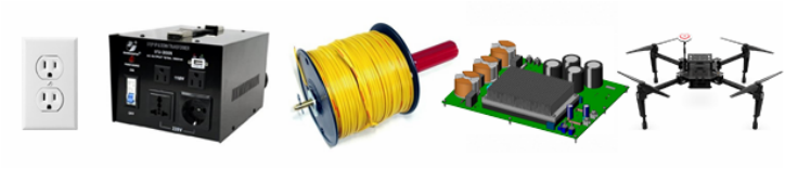
To power the drone, household 110VAC will be stepped up to 240VAC using a voltage transformer. The transformer will connect to the powered tether cable via a NEMA 620 three blade plug. The tether will use three 22AWG wire that will be braided with heat shrink every couple feet. At the drone, the tether will connect to the ACDC converter power supply with ring terminals and the connection will be strain relieved. The power supply will mount with zip ties to the bottom of the drone for convective cooling from the propellers. The ACDC converter will connect to the stock drone power input with a short cable and quick disconnect terminals.
|
Tether Management System
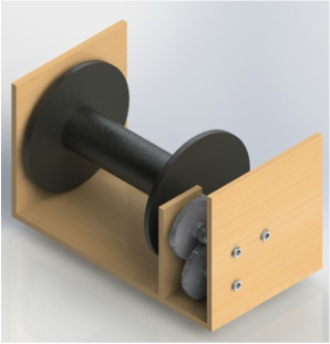
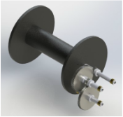
To manage the tether, a spooling mechanism will be used. Tension will be applied to the tether in order to prevent tangling with the drone’s propellers. To apply the tension, constant force springs will be used. There are three main subassemblies of the tether management system: the spool and gear subassembly, the spring subassembly, and the fixture subassembly. Each of these subassemblies and their interaction with one another is described below in detail. Drawings and exploded views for each subassembly, and the entire mechanism, may be found in the appendix with the Bill of Materials. To the right is a rendered image of the entire tethering assembly. As shown in the image below, the spool is mounted on a shaft, which transfers through the gears and finally to the springs. The fixture subassembly holds it all in place. |
|
Gear Subassembly
Throughout the process of unreeling, the spool will rotate approximately 110 times, while the springs have a maximum capability to be unwound about 10 times. In order to solve this issue, the rotation of the spool will be geared down by a ratio of 14:1 to assure that the springs will not be overwound. The gear assembly will interface both with the spool and the springs to create a gear reduction between the spool and the springs.
Throughout the process of unreeling, the spool will rotate approximately 110 times, while the springs have a maximum capability to be unwound about 10 times. In order to solve this issue, the rotation of the spool will be geared down by a ratio of 14:1 to assure that the springs will not be overwound. The gear assembly will interface both with the spool and the springs to create a gear reduction between the spool and the springs.
Spring Subassembly
In order to maintain constant tension without creating too large of a force on the drone, the goal was initially to apply a pound of force to the tether. After reconsidering the total load on the drone, our team determined that one third of a pound would be a large enough force. This force will prevent the tether from getting tangled in the rotors of the drone since the tether will be well maintained and taut. We plan on using a constant force spring, since the force will not vary during the drone’s flight. The constant force spring will be mechanically attached to the shaft where the gear system begins.
In order to maintain constant tension without creating too large of a force on the drone, the goal was initially to apply a pound of force to the tether. After reconsidering the total load on the drone, our team determined that one third of a pound would be a large enough force. This force will prevent the tether from getting tangled in the rotors of the drone since the tether will be well maintained and taut. We plan on using a constant force spring, since the force will not vary during the drone’s flight. The constant force spring will be mechanically attached to the shaft where the gear system begins.
Fixture Subassembly
The fixture subassembly provides support for the gear shafts and the springs. The fixture pieces will be manufactured from plywood, and holes will be laser cut to support the shafts. Oil embedded bronze bushings will allow the shafts to spin with little resistance, and snap rings will be used to hold the shafts in place along the horizontal axis, and snap ring grooves will be machined into the shafts. All shafts will be supported on either side by a fixture so that none are cantilevered.
The fixture subassembly provides support for the gear shafts and the springs. The fixture pieces will be manufactured from plywood, and holes will be laser cut to support the shafts. Oil embedded bronze bushings will allow the shafts to spin with little resistance, and snap rings will be used to hold the shafts in place along the horizontal axis, and snap ring grooves will be machined into the shafts. All shafts will be supported on either side by a fixture so that none are cantilevered.
Parameter Analysis
Power System
The powering system is almost complete and needs to be integrated with the reel to be completed. Using a household 110V outlet the voltage is stepped up to 240V using a 5000W voltage transformer and then sent through 22 Gauge wire to the power supply onboard the drone. This voltage transformer was chosen because it is capable of supplying 5 times the max output of the onboard power supply. This buffer is needed during system startup where there will be a high inrush current. The onboard power supply draws 6A at 200VAC during full 1000W load. The wire selected can handle up to 10A at 300VAC which is comfortably above what the drone will require and has other desirable qualities such as its small diameter and flexibility. Lastly, the TDKLambda power supply has a 1000W output which leaves a large power buffer for additional components. All of the components work in unison to supply the drone with safe, reliable power through our 100ft cable.
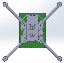
The unaddressed issues with the power system are heat and weight. The TDKLambda power supply weighs 4.7 lb, including a 1.5 lb heat sink. The drone can fly with a 6.2 lb payload without the stock battery. When hovering at 100ft, the tether will weigh 1lb and the total payload will still be able to carried by the drone. The power supply will be mounted to the bottom of the drone chassis. The power supply board is slightly larger than the chassis of the drone and may affect the downward thrust from the propellers. A top view of the drone and power supply can be seen in the figure to the right. The power supply will also change the center of gravity of the drone and may change handling and flying characteristics of the drone.
The unaddressed issues with the power system are heat and weight. The TDKLambda power supply weighs 4.7 lb, including a 1.5 lb heat sink. The drone can fly with a 6.2 lb payload without the stock battery. When hovering at 100ft, the tether will weigh 1lb and the total payload will still be able to carried by the drone. The power supply will be mounted to the bottom of the drone chassis. The power supply board is slightly larger than the chassis of the drone and may affect the downward thrust from the propellers. A top view of the drone and power supply can be seen in the figure to the right. The power supply will also change the center of gravity of the drone and may change handling and flying characteristics of the drone.
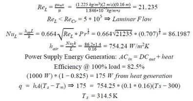
The heat generated by the components on the power supply is minimized by a heat sink. However, this heat sink weighs 1.5 lbs which is a large portion of the maximum payload so it would be ideal to remove the heat sink and allow for the airflow generated by the drone propellers to convectively cool the drone without the need for a heat sink. To the right are heat generation calculations to confirm that the heat sink is not necessary.
The power supply components are rated at 412 K which means that the airflow over the power supply will cool the components enough that the 1.5 lb heat sink can be removed.
The power supply components are rated at 412 K which means that the airflow over the power supply will cool the components enough that the 1.5 lb heat sink can be removed.
Tether Management System
The tether management system is designed to apply tension to the tether to limit the possibility of tangling with the propellers. The tension that is applied to the tether drives all material selections, as any material we choose must be able to withstand the tensile forces applied by the springs. In addition, the material selection is also driven by manufacturability. Some materials lend themselves to the manufacturing tools that are available to us, and hence would be more desirable to use.
Gear Reduction
A gear reduction is necessary to prevent the springs from being overwound. Since the spool must spin 110 times and the spring may only be unwound 10 times, we decide that a reduction ratio of 14:1 will be sufficient in keeping the spring safe. To achieve this, a shaft rotating with the spool will have a 20 tooth gear also mounted on it. This gear will interface with another gear of 75 teeth. This provides a gear ratio of 3.75:1. On that same shaft with the 75 tooth gear is another 20 tooth gear, which interfaces with an addition 75 tooth gear on a separate shaft, providing a gear ratio again of 3.75:1. The total gear ratio between these two step down is 14:1 reduction. As the drone takes off, for every 14 times that the spool is spun, the springs will rotate through just a single rotation, assuring that the springs will not be damaged or come loose in the process. The gears will have a diametral pitch of 16 teeth/inch such that the gears have coarse enough teeth to handle the load. For any larger diametral pitch, however, the gears become unreasonably large in diameter such that they do not fit well within the mechanism.
Spring Specification
Due to the gear reduction, the force applied at the reel from a single force spring will be reduced. Our goal is to apply one pound of tension to the wire tether. Therefore, we will need to place multiple force springs in series. We will use constant force springs to assure that the tension on the line doesn’t vary with time. To calculate the force on the tether, we begin by calculating the torque applied by a single spring.
Torque is equal to the load, P, multiplied by half the diameter of the spring. For the spring specified for use, P = 10.6 lbs and R = 0.675 in., so we find that Tspring = 10.6 * 0.675 in = 0.5963 ft lbs.
In the scenario where there is no gear reduction between the spring and the spool, we can note that: Tspring = Tspool
Thus, after the reduction, we can state that the torque is reduced proportionally to the gear reduction.
Tspool,reduced = Tspool / Reduction = .5963 / 14 = 0.043 ft lbs
From the torque, the force is calculated simply by the following equation:
Fspool,reduced = Tspool,reduced / Rspool = 0.043 / 1.75 in. = 0.3 lbs
Thus, if we want to maintain about a pound of tension on the tether, we will need three of these springs in parallel. These springs will be mounted on the same shaft as the 43 tooth gear, such that they will unwind once for every 13 rotations of the spool, providing a constant resistive force to the spool. A cylindrical plastic adapter will be used to attach the springs to the ¾ inch shaft.
Delrin Laser Cut Gears
Because we chose to use gears that are not commonly available stock parts, we will need to prototype our own. The gear profiles are created using GibbsCAM gear dialogue which takes input of pressure angle, diametral pitch, pitch diameter, etc. Originally we thought the simplest way to prototype these gears was to use 3D printing. After consulting the Etcheverry student machine shop staff, we will instead manufacture the gears by laser cutting delrin. The laser cutter will provide better resolution and allow for more accurately manufactured gears as well as save cost. Manufacturing will also be faster, only taking 10 minutes to cut the delrin sheets instead of hours to print ABS. Delrin also has better wear properties and more than double the ultimate strength. To assure that the delrin is a sufficiently strong material to handle the load applied by the springs, it is necessary to calculate the force per unit area applied to the gears and compare that to the strength of delrin. The force applied by the springs is Psprings = 10.6 * 3 = 31.8 lbs
Now calculating the stress applied to one of the teeth,
σ = F/A = 31.8 lbs / 0.07 in2 = 455 psi
σultimate = 11100 psi
Since the ultimate strength is greater than the stress we will apply to the spring, we can be sure that the delrin material is sufficiently strong to handle the load applied to it. Because we chose to laser cut the gears, they must have a 2 dimensional profile, so the gears will no longer have the collar for the set screw that was originally designed. Without a collar, the issue arises of how to fix the gears onto the shaft to transfer the torque. After discussing this with the technicians at the machine shop, we decided that laser cutting a collar that we could mechanically fix onto the gears would be best. The collar will be attached to the gears with two screws, and a set screw will attach the collar, and hence the gear to the shaft.
ABS Shaft Tubing
The shaft will be made from ABS tubing. Tubing is required because the tether will run through the shaft and out to the rotary device. Since the wires will be running through the shaft, it is preferable to have a material that is not conductive for safety purposes. Hence, a plastic material is ideal. The shaft itself will undergo relatively little stress since only a pound of force is to be applied at any time. The tubing is sufficiently strong to handle the pound of force with relatively little deflection.
Plywood Base Structure
Plywood was chosen for the base structure so that it can be easily and precisely manufactured using a laser cutter. Precision is important in manufacturing the base structure to assure proper meshing of the gears. The precision of the laser cutter will provide the precision we need. The wood is easily screwed together with wood fastening screws, providing the adhesive strength between the panels.
Final Design
The design has not altered largely from the initial concept description. The base of our tethered drone will contain a 220V outlet converter and our reeling device in a wooden box that can connect to a wall power outlet. Fastened under the base of our drone will be a 1000W ACDC converter that is enclosed in a tight fitting plastic case to protect the components. This case will have cutouts to allow for airflow to help maintain a low temperature for the board. In order to fit the board more closely to the body of the drone, the case that initially contained the battery will be removed from the base of the drone. The final tether wire will be made from three 22 gauge stranded wires that carry up to 300V AC. The wires in the tether will be braided together and wrapped in heat shrink every couple of feet in order to keep the wires together and attached to the drone. The overall weight of the tether should be 1lb. The mechanical reel will operate based on continual tension applied by a combination of constant force springs. The gear reduction of 14:1 will allow the spool to wrap 14 times for every turn of the force springs.
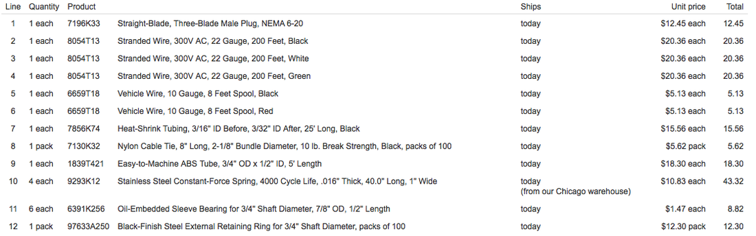
A large amount of the supplies for our project were ordered from McMaster Carr which can be seen in the figure below . The drawings for all parts that will be machined by Team SkyBison can be found in the appendix. These parts include the reel fixture base which will be made from wood and the gear shafts which will be manufactured from ABS tube stock.
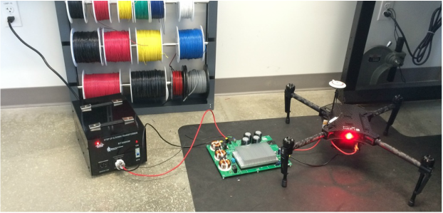
The initial testing for the power system has been completed and the drone successfully powered on, the system can be seen in the figure below. Household 110VAC was transformed to 240VAC and then converted to 24VDC to power the drone.
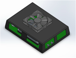
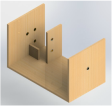
Another design decision is how to protect the power supply on the drone. We have been designing a case that would have a fan to help circulate air and slots on the sides to permit airflow. This case would protect the power supply while providing enough airflow to remove the heavy heat sink which would reduce the overall weight. We plan to print the case with a 3D printer so that it will be light weight. An initial design for our case can be seen to the right.
Problem Analysis
The demands of the drone can be roughly estimated based upon battery capacity and flight time. With a 2.2 lb payload on the drone, the estimated hover power draw is approximately 460 W. The actual power demands for a loaded drone thrusting upwards will be greater. This is why a power supply with double the hovering power wattage is chosen. Although removing the battery and replacing it with a power supply seems simple, there may be some underlying challenges. The battery acts as a large capacitor and with the ground replaced by an AC power supply, ground reference difference may be an issue for the drone electrical system. This will need to be checked with testing. The critical parts in the power system will be the tether wire gauge and the power supply. Power supply heat and weight and tether wire diameter and weight design will need to be validated be during testing.
After receiving the necessary parts for our power solution, we ran into a couple potential issues. The AC to DC converter that we purchased to attach in the drone and allow us to pass an AC current up the wire is large and heavy. As discussed in parameter analysis, our group has been focusing on a way to attach and protect this device. Our goal is to create enough ventilation that we can remove the heat sink on the board since that is the greatest contributor to the board weight.
The two main challenges with the reel will be spooling and tension. We must ensure that the tether will reel in and out with no complications, such as tangling or falling off the spool. We will follow the model of a fishing reel for this purpose. We also must calibrate the tension mechanism to provide appropriate force for all drone heights up to 100 feet. This will require a thorough understanding of the tension springs we will use. The critical parts in the tether management system will be the gears and constant force springs. The tension of the tether will need to be checked during testing.
